
Another Article with back story…
at about 4:20 PM, I was getting ready to leave work, when my phone rang. Bryan was asking what I knew about whetstone bridges.
While it’s been many years since I was first licensed, and decided I wanted to build one that I saw either in a QST magazine, or an ARRL Handbook, I remembered the basic concept – a bridge of 3 resistors and terminals for the load under test. When the load under test matches the impedance of the 3 remaining bridge resistors, a null will be indicated.. This didn’t help much, as I couldn’t remember the way the excitation voltage or measurement device were connected, so I promised to look it up and figure out how the math plays into it when I got home.
Now – there are a couple of basic electrical engineering concepts at play here:
1) Voltage divider- When two resistors are placed in series across a voltage, the voltage across each resistor will be proportional to the size of the resistor. Simple? well… sort of. Imagine a 10 volt source, and imagine we have two resistors placed in series across that voltage:
Figure 1: Basic Voltage Divider
Now, if R1 = R2, the voltage across the two resistors will be equal, in this case, 10V / 2 = 5 volts.
If R1 is NOT equal to R2, then some simple math is involved… From the article here:http://en.wikipedia.org/wiki/Voltage_divider
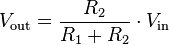
Where: Vin = the source voltage
Vout = Voltage across R2. If the voltage across R1 is desired, either subtract
Vout from Vin, or substitute V1 in the numerator of the above formula.
Now, the second concept is the current divider. A bit more complex, but not much.
In a Current Divider, the current from the supply will be divided inversely proportionally to the parallel resistances across the supply. A current divider is shown below:

Let’s start by assuming our source is now a 10 amp source. If R1 = R2, then, similar to what we had above, the current flowing through R1 and R2 would be 5 amps a piece.
If R1 is NOT equal to R2, it gets a bit more complex. From the article here:http://en.wikipedia.org/wiki/Current_divider, the formula for a current divider is shown below

Where Rt = the total equivalent parallel resistance across the source (the inverse of the sum of the inverses)
It = the total current form the source
Rx = the resistor in question
Ix = the current through the resistor in question
Now… back to the Whetstone Bridge…
What does a whetstone bridge look like?
Ahh, the wonders of Wikipedia.. from http://en.wikipedia.org/wiki/Wheatstone_bridge:

What happens here? well, let’s change the schematic a little for illustrative purposes:

Inspecting a little closer, what is going on here? Well – there’s a current divider between the combination of R1/R2, and R3/R4. Additionally, each of these branches is forming a voltage divider. We’ll ignore the current divider for the time being. Since the voltage across the two dividers is the same, as they are connected to the same source, we can use that to our advantage.
Keeping in mind from the original schematic that R2 is variable, note that R1, R3, and R4 are all the same resistance value. Let’s use them as 10 ohm resistors for this discussion. We’ll make the source a 20 volt source for simplicity of the math.
Since the resistances of the R3/R4 divider are fixed and equal, the voltages across R3 and R4 are the same – 10 volts.
Now, what about R1/R2? if they are equal, then the same condition will exist as in R3/R4 – the voltage across both resistors will be 10 volts.
What about the voltmeter above? (the circle with the V in it). What is it doing? it’s measuring the differencebetween the voltage across R2 and the voltage across R4. How is this significant? well, setting aside the example above, if this bridge was being used in a typical two way radio system, the resistor values would be 50 ohms. as Rs is varied, the meter will change. Looking ahead, if R2 was, say, an antenna system, the voltmeter would read zero volts when R2 was equal to 50 ohms, or when it was matched to the resistor values used to make up the rest of the bridge.
going back to the example, now… When the value of R2 is increased from 10 ohms to, say, 30 ohms, what will happen? Using the formula above, (30 / (30+10)) * 20 = 15 volts across R2, and 5 volts across R1. R4 will still have 10 volts across it. The meter will indicate a voltage difference of 5 volts, indicating that the resistance across R2 is not equal to the other resistors.
Now, let’s assume R2 drops to 5 ohms. the formula becomes: (5 / (5+10)) *20 = 6.67 volts. The meter will now indicate a difference between the voltage across R2 and the voltage across R4 of 5 volts.
Practically speaking, the voltmeter used should be capable of displaying both a positive and negative voltage difference. This is easily achieved using a center zeroed meter, or an electronic indicator. alternatively, a diode bridge rectifier could be used to change the voltage polarity when working with DC circuits.
Now- what is this thing good for?
Well, as stated before, if the fixed resistors are set to 50 ohms, then R2 may be replaced with a coaxial jack, and the voltage source may also be replaced with a coaxial jack. The source jack is connected to an RF source (transmitter, signal generator, etc.), and the R2 jack is connected to a device to be tested – most likely an antenna. The antenna may be adjusted until the meter shows a null reading, which will indicate that the device is closely matched to 50 ohms. a simple way to tune an antenna without messing around with “setting forward power”, etc.
Keeping all of that in mind, this could serve for the basis of building other circuits. Using something such as this as the basis for an auto tuner circuit, along with an A/D converter in place of the meter would allow for a microprocessor to be able to tuner the antenna system for minimum VSWR. This may have some applications in place of measurements typically using the return loss method, if a relative measurement is desired. The challenge here is to appropriately size the resistors to avoid damage. This circuit is not something that can be left in during transmitter operation, as it will result in lost power due to the resistors. If, however, a switching mechanism can be included, this circuit could be easily switched in and out of the transmission line path to verify antenna performance at a given frequency. Another advantage to this method is that a very low power RF source can be used, and high dynamic range of the measurement device is not critical. Additionally, higher power versions can be made, if that is a desirable characteristic.
In addition to RF circuits, this type of circuit could be used for items such as strain gauges in mechanical vibration testing – the meter swing could easily indicate strain. Since the strain gauge presents a varying resistance with the amount of strain present, the meter would swing in one direction or another as the strain varied. Replace the voltmeter with an oscilloscope, and strain versus time is easily plotted. Add another oscilloscope channel indicating the strain stimulus (an actuator or some other source of strain on the item under test), and breaking points can easily be shown.