Another “older” project I want to post now, just for others to benefit from my learning experience…
For years, I’ve wanted a repeater to tinker with. Back as far as my time in Rolla, I’ve had most of the parts, but have always been short on the final steps.
It all started with an interest in a 6 Meter Repeater, because the Yaesu VX5 had the capability…
I was given a pile of Motorola MOTRACs – I had them mounted in a chassis, and functioning, pending crystals. The tube power supplies singing when they went into transmit mode was a bit tough – and I didn’t have a power supply that would handle them well.
The power supplies came and went, I got rid of the MOTRACs, and ended up acquiring some MASTR II low band mobiles. These stuck around (I still have access to them, but W0ODS is also interested, so i tossed them in his lap to play with…), and were a lot more user friendly from a tuning, power, and maintenance standpoint.
Somewhere in that timeframe, I acquired an FF Systems FF800 – long story short, I bought one of the original units (as in “prototype”), and paid for an upgrade. This got me a little more interested. Throughout my post graduation time in St. Louis, I had not really acquired much in the way of equipment. When the controller was purchased, I also bought the W0LLU 220 MHz system from St. James, MO (long since defunct) – but the hodgepodge of equipment was not really in any state to be brought back to life, so most of that got recycled.
Moved to Cedar Rapids, IA in 2007 for work. Sometime after this, I had a work trip to San Antonio, which allowed me to get to Round Rock to meet up with KE0FF and actually get my upgraded FF800 from Joe – fun stuff to get home in my luggage! Then there was more free stuff, since I acquired a controller… I needed radios. Someone on the Radio Farm gave me a Repco (Aerotron, i believe) self-contained repeater. This was a nice little unit… a little tinkering, and I had it working with the controller, but not retuned. I always hated messing with crystals. So close. Again, progress stalled. … no point in getting too into the controller until I got a functioning RF section.
Around this same time, I began tinkering with the necessary cabling to get Echolink working with the FF800 (basically building the computer<-> controller interface for audio / TR switching). Like I said, life put the brakes on this project for a while. At this same time, however, I spoke with Ron, KX9Y, and got permission to put my machine on 443.825, so long as I did not interfere with the N0MA machine on 443.800 MHz. Since I planned for lower power, and was not really shooting for a wide coverage machine, this should not be a problem. My goal was to Mirror the W0EEE UHF machine, to some degree – just because I could.
Fast forward a bit… in 2012, “wideband pulls” became a huge topic among the radio communities. With the FCC requiring that commercial and public safety users switch to narrowband channels to conserve spectrum, older, non-compliant, equipment began to show up as widely available, since the high paying customers wouldn’t buy them. I knew that this would eventually enable me to get my paws on a synthesized repeater in some way, shape or form, but I didn’t know when. When a MASTR II cabinet became available, I jumped on it, knowing that the cabinet and power supply alone could be great assets – especially given the pristine condition of this equipment (it was stored in a water tower as part of the emergency siren system).
While I was searching for crystals for the MASTR II system (no point in interfacing the controller until the RF section works, remember?), I was contacted about a Motorola R100 needing a home. The R100 was a circa 1986 synthesized (Radius line) machine. I jumped on the chance.
The day I received it (28 December 2012, right on schedule, thanks UPS), I built the programming interface from the schematic at Repeater Builder’s R100 page. The same night (well… the next morning – it was about 1:30AM when I finished the necessary prep work), I managed to get it connected to a computer to test it out – amazing.. First time success.
Unfortunately, that was an insomnia night, and the 4 year old was up extra early the next morning. Sometime the next day, I got the repeater programmed into the ham band (I sure am glad I kept this old Toshiba 486 laptop… the HDD no longer works, but I can boot from a DOS boot disk (did you know Windows 8 can still handle Floppy Disk Drives? well, how else am I going to get the files available from the web onto that old 486?)
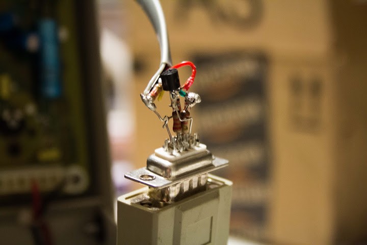
The programming interface – I admit… It’s ugly as all get out, but it DOES work. The resistors were all salvaged from old PC boards I pulled the components from. The only difference between mine and the schematic is the use of a 22k ohm resistor in place of the 27k shown on the schematic at the base of the PNP transistor.
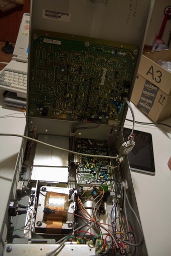
The R100 station getting programmed – the RJ11 lead SHOULD be a little longer, but I used what I had on hand – like I mentioned before – most of the components were salvaged or reused!
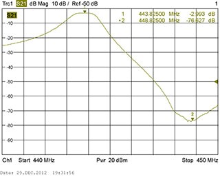
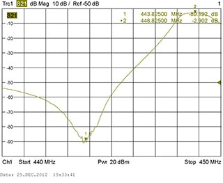
The next day (29 Dec 2012), I hauled my UHF duplexer in to work to tune it to the frequencies I had chosen. I like being in an EMI lab – so many toys, A Rohde & Schwarz ZVL-3 network analyzer made tuning a cinch, since I could quickly see where the notches and nulls were moving to. It took me about an hour to tune them, but half of that was trying to find the equipment I needed, cables, calibrating the analyzer, etc.
Not too bad, 3 dB loss on either side. I was hoping for a little less.. I had one side down to 1.4 dB – but they DO interact with each other. Had I used the ZVA-40, i could have watched alll the interactions, since that is a 4 port analyzer. Maybe next time.
Now all that was left was the RF section alignment. Lucky for me W0ODS has a communication analyzer he is willing to loan me – this will allow me to tune for SINAD and all that other good stuff, per the maintenance manual for the R100…. well, that and figuring out how to interface it to the FF800… since my R100 does not have the J Aux connector, it will be a little more involved getting the controller connected.
It was a late night getting the receiver tuned, but that went VERY quickly. Just follow the service manual.
The transmitter… not so much. I knew the VCO was not locking, but the control was doing NOTHING. Turns out, it was the wrong control. Motorola identified everything on one diagram, but failed to mention that the transmit adjustments were on the bottom side of the transmit module, and in order to align it, it had to be pulled from the chassis! The two radio modules (one TX, one RX) look almost identical. The controller portions ARE identical PCBs – the Receive control board even has silkscreens for RF power. Once I read the Repeater Builder site a little further, I found the instructions explaining all this. everything was pretty easy. Got it working with 10 minutes to spare in 2012. K9FRT/R will be a reality early in 2013!
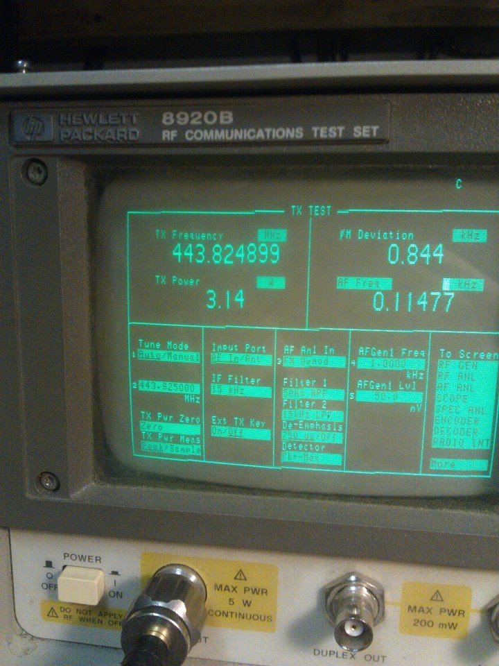
Since the unit was capable of 2 – 10 watts out (well, it would go way below 2, but I’m assuming Motorola decided on 2 watts for a minimum specification for a reason… usually stability) – I was limited in the output power I could choose… I decided on Pi. Now… can the controller say “Pi watts out”?
Well, new year’s day (night?), I made some real progress. I found the PTT, COS, and transmit audio points i needed. The receive audio point is escaping me a little. I found a line carrying the signal i needed, but I can’t find it on the controller PCB. As of this point, I’m still trying to keep all my connections on the R100 controller board (less chance for messing up the RF sections!)
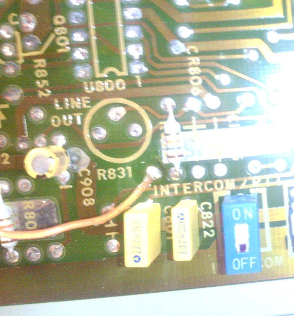
The Transmit Audio was the easiest to find, since the local handset has a nice via right next to the jack which happens to connect to the mic line. This is DC biased, so a capacitor was necessary to AC couple the audio in. Since I didn’t have a NICE selection of caps, I did some trial and error with what I had to find one that passed a nice signal level through to the transmitter (in this case, a receive radio on frequency was necessary – a VX7 and an old Radio Shack scanner worked well). Just below that point is also a via on the ground plane – a nice place to tie in the controller ground. I apologize for the image quality on the next few shots, but the SLR was upstairs, and the phone was dead… so I reverted to the inexpensive Chinese android tablet.
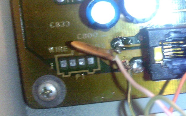
Note that these images should have enough “extra” stuff in the shot to illustrate where this is on the PCB. In this case, the RJ45 you see is the “service handset” jack, located in the lower left corner of the board. I cleaned up the solder joints after this. Additionally, since the FF800 has a ground on the TX and RX ports, both shields are tied to the ground point shown as the bottom connection,
I figured out where the PTT connection needed to be based on where the J Aux interface board connections were pictured (on the Repeater Builder website (Link)- since I don’t have the J Aux connector or board). I tried this method for the rest of the connections, to no avail. There are a LOT of interface wires – I didn’t completely check the J5 RAT connector. but… PTT:
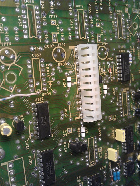
Note that this is installed right next to he manual PTT switch on the controller board – the switch shown is the intercom switch – and you can barely see the edge of the PTT switch on the bottom right edge of the image above. This is where the J AUX interface board pulls PTT.
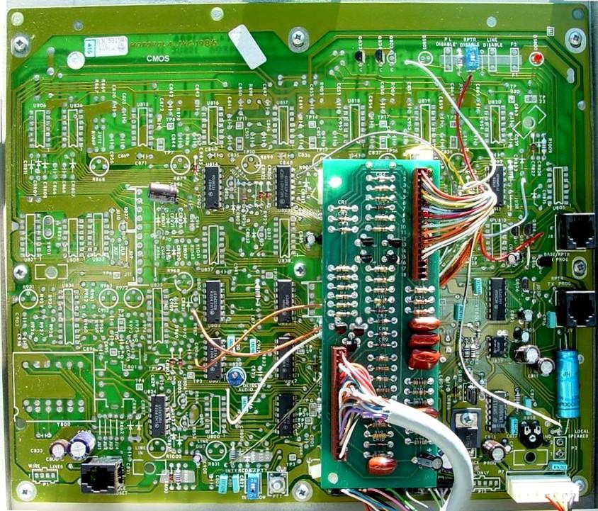
COS and PL detect are different functions. In this case, I wanted PL detect, since I plan on running the machine with a PL and am not using my controller as a PL decoder. The Receiver module has both PL Detect AND COS lines, so it’s a matter of picking one. I discovered this point by looking at the connector pinout, then trying to trace the lines back to appropriate vias on the PCB. in this case, the point I used was an accidental discovery, but it works perfect as an active low PL detect point.
RX Audio seems to be the biggest challenge I have to face at this point. I have a good line off the receiver interface connector (“Flat audio”, an orange wire), but cannot find anypace on the board where it has a direct via to the top side ot the board, where I am working. Since the service manual I have is very limited (I have the version that Repeater Builder posted online, which has limited quality scans, unfortunately… high quality scans, or the real thing, would help a LOT!). This will likely require pulling the controller board out of the chassis and following traces on the back to find a via or good point to connect the wire to.
This is not to say I did not get any on air testing done, though! I tapped into the connector on that orange wire I mentioned, and ran the transmitter into an antenna on my roof, then rebooted the FF800 to get it to transmit. I also did a little transmitting on my VX7 to get the repeater to operate.
Luckily, N0AGL was still awake and had a radio nearby – granted, he’s only 500 meters away, and the repeater was running 3.14 watts, he could hear it and verified that the audio was acceptable. Obviously, since i had a limited antenna on receive (and no duplexer connected yet), he couldn’t hit it – it is a good start.
2 January – I found a pickoff point for the RX audio on the control board. Looks like there IS a pin on the RAT connector that has the “flat audio” line. Got that connected, turned up the RX audio in the controller, and things are improving. Still need to do some tweaking, but now it’s a fully functional repeater…. well… sans the duplexer, which is still not connected (need to build some RF cables for it).
Update: tinny audio, and weak. turned up the POT in the FF800 (digital RX audio pot) – that fixed the volume… but the audio still sounded tinny. Turns out “flat” audio is not what I thought… it’s the pre-emphasis audio – still adjusted for part of the modulation process. I’ll need to do some digging around to find the right level de-emphasis audio. This is still not a bad find, as far as audio goes, though – could be useful for tone decoders, and the like. The repeater has, however, now spent it’s first couple hours on the air with the duplexer. I might try a little tweaking on the RX side, based on the noise I heard… though I need a simplex link on-channel form the same distance to verify whether i was achieving acceptable performance (Red Cross building to my house).
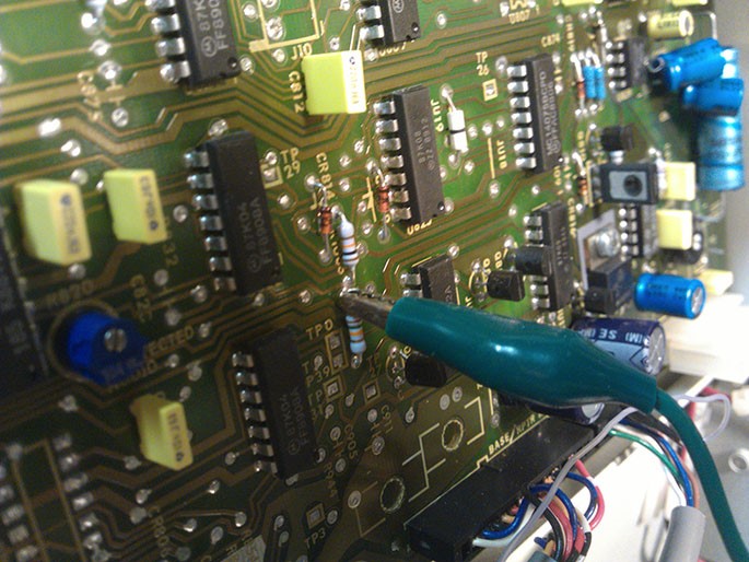
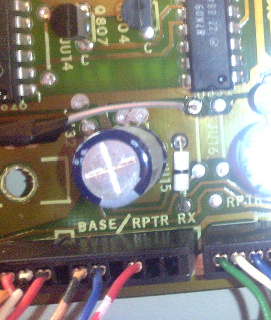
Turns out one of the points I tested earlier works just fine for this purpose. The junction of these two resistors has what has been described as “very natural” audio. While the audio sounded nice, I’m thinking I need a little duplexer refinement. Then again, the antenna I am using (a discone) and long coax run,, not to mention the fact that the repeater is a bit far from the original frequency… might just all add up. It did, as is, however, survive it’s first QSO between people other than myself and N0AGL – AA0KW and KX9Y chatted briefly after my HT died doing audio checks.