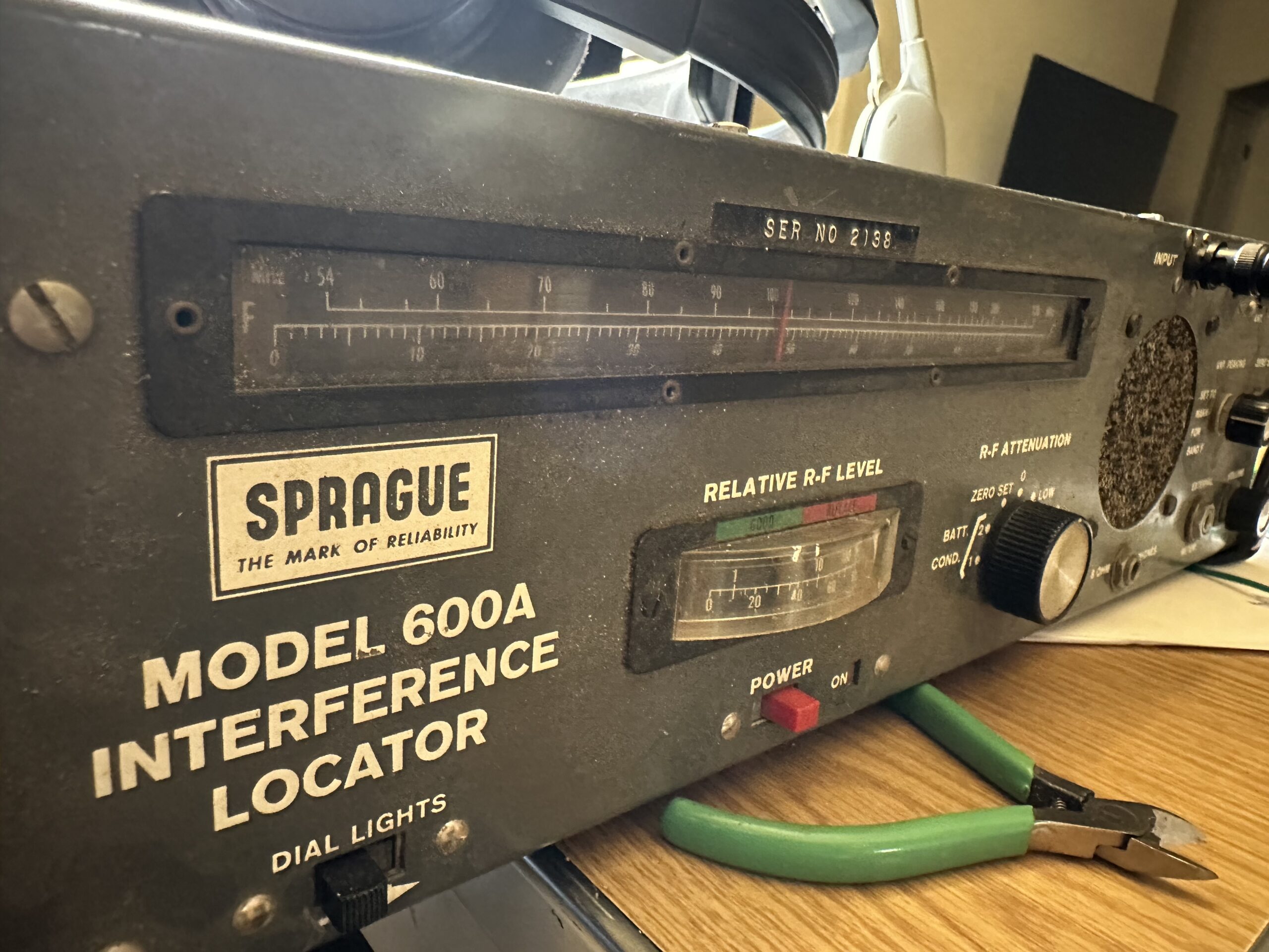
Many years ago, I was blessed to get a Sprague 600A Interference Locator from the estate of my Elmer, WB9KHR. As an EMI Engineer, this was just COOL. It was old, and it’s no Rohde & Schwarz FSH-18, but it’s some EMI history – a bit like having an EMC-25 in the corner. Moreover, even today, I can’t find much online about it. I have a manual, and I found a digital copy on BAMA – though some of the details in the schematic are hard to read due to the scan resolution. I may work on a better scan and help them out. All that said – I haven’t even seen one of these online. I’ve seen references to the Model 500, and there’s a handful of sites hosting the manual, but no-one else seems to have worked on, or with, one.
When I got the thing home, and inspected it, I found that the batteries inside had corroded, leaked, and were just gone. Unfortunately, it caused a little corrosion inside the analyzer, but nothing seemed to terribly bad. I briefly searched for battery options, but didn’t see exact replacements. The analyzer had the following power requirements:
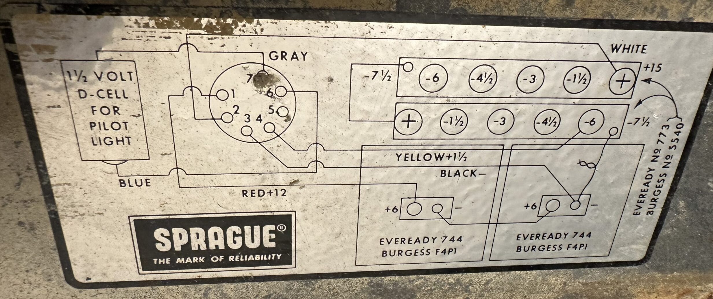
- +15V supplied by two 7.5V batteries in series
- +1.5V, referenced to the – terminal on the bottom 7.5V battery mentioned above (apparently these specific batteries had one or more taps on the different cells). This is a bias voltage only, and doesn’t draw a significant current
- +12V supplied by two 6V batteries in series
- +1.5V supplied by a “D” Cell for panel lighting
I searched for “matching voltage” LiPO packs (drop in replacements), and considered ordering some rechargeable packs. This wasn’t “easy”. Then I started inspecting the schematic in the manual, and the battery wiring diagram inside the back lid. I noted that the 15V and 12V battery stacks had their “bottom” battery – terminals tied together. And the manual showed these to be tied to chassis. So this means three of the power requirements were all referenced to the same point. This would allow one larger pack to be used, along with some buck regulators to set the lower voltages. I immediately thought about getting a 15V pack, and adding some linear regulators inside the case (7812, and an adjustable set to 1.5V).
Life happened, and this project got shelved. I actually had started acquiring some components, and put them in a box, which was stored away with the analyzer, so I could come back to this some day.
More recently, I decided this project needed to be finished. Interestingly enough, I also re-read some of my own posts here, and came to a realization – I already had a suitable battery pack. The Dewalt (compatible) packs I’ve been planning for QRP use, emergency cell phone charging, etc. At 20V, this is MORE than sufficient to use as a starting point. The problem is getting 20V out, and not getting an adaptor with only a 12V output.
Now, Peter had said “We’re not going to fix this as good as new, we’re going to fix it BETTER than new”. If I can make this thing use a single battery, and a rechargeable one at that, I think I’ve met his requirements.
Doing some amazon shopping, I found this:
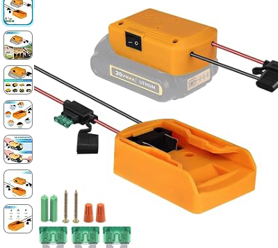
These adaptors are SIMILAR to my 12V adaptor, but they’re apparently sold for upgrading power wheels trucks – and they put out the battery’s native voltage… no active components! On top of all that, I like the fuse and built in power switch. Adds a degree of protection when I’m testing.
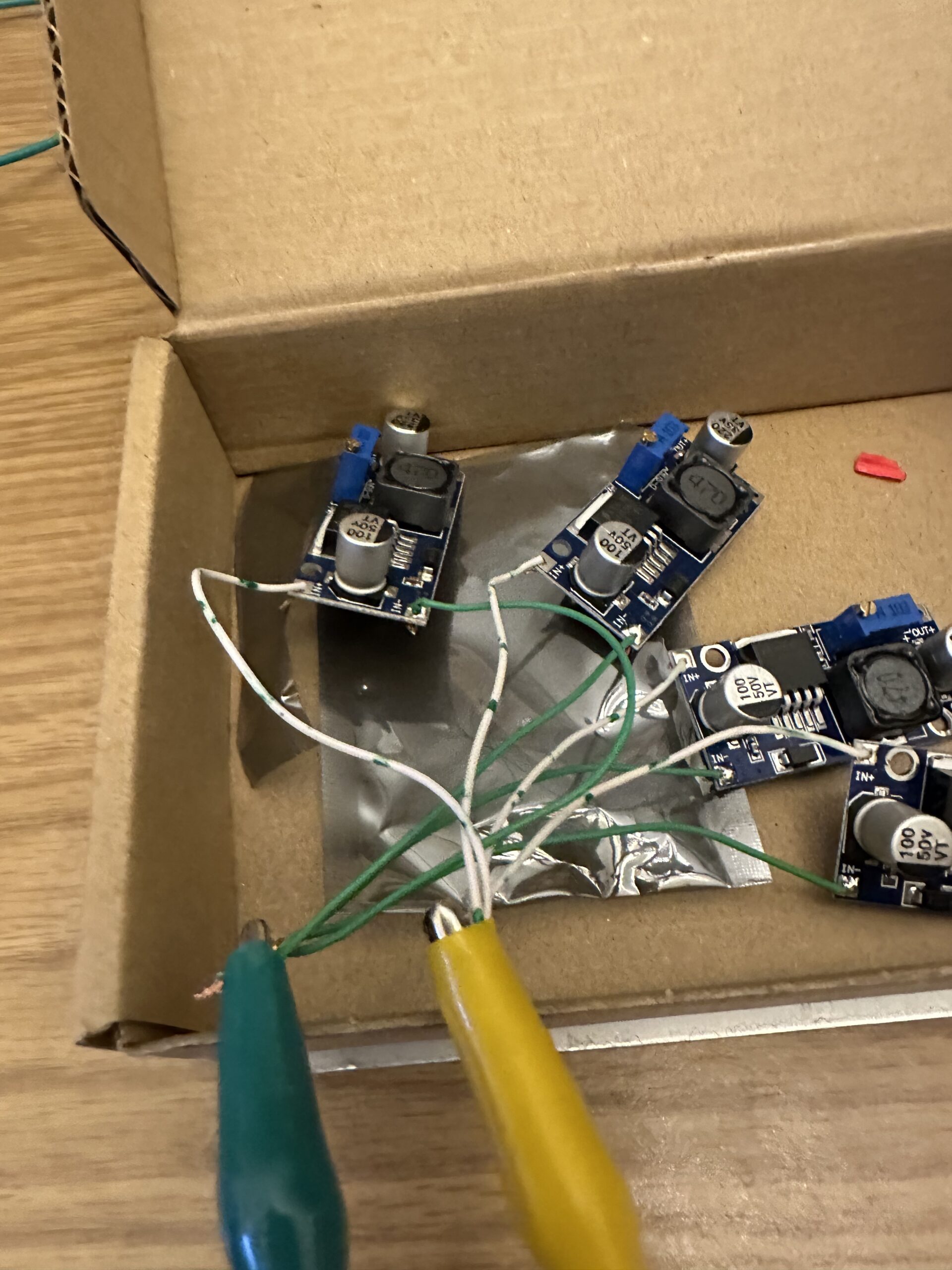
Now that I had a power source, I needed to figure out how to buck the voltage to what I needed. More Amazon shopping. I came across “Valefod 6 Pack LM2596 DC to DC High Efficiency Voltage Regulator 3.2-35V to 1.25-30V Buck Converter DIY Power Supply Step-Down Module”. Six DC-DC converters for about 10 bucks.
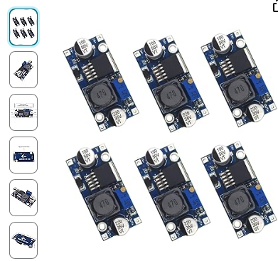
I would have LIKED A single board with 4 converters on it, but that wasn’t an option – the only types that seemed to exist either had 12V, 5V, and an adjustable output, or included DC voltage readouts and were way more expensive. When these arrived, I got to work, set them to +15, +12, +1.5, and +1.5V, and assembled a stackup
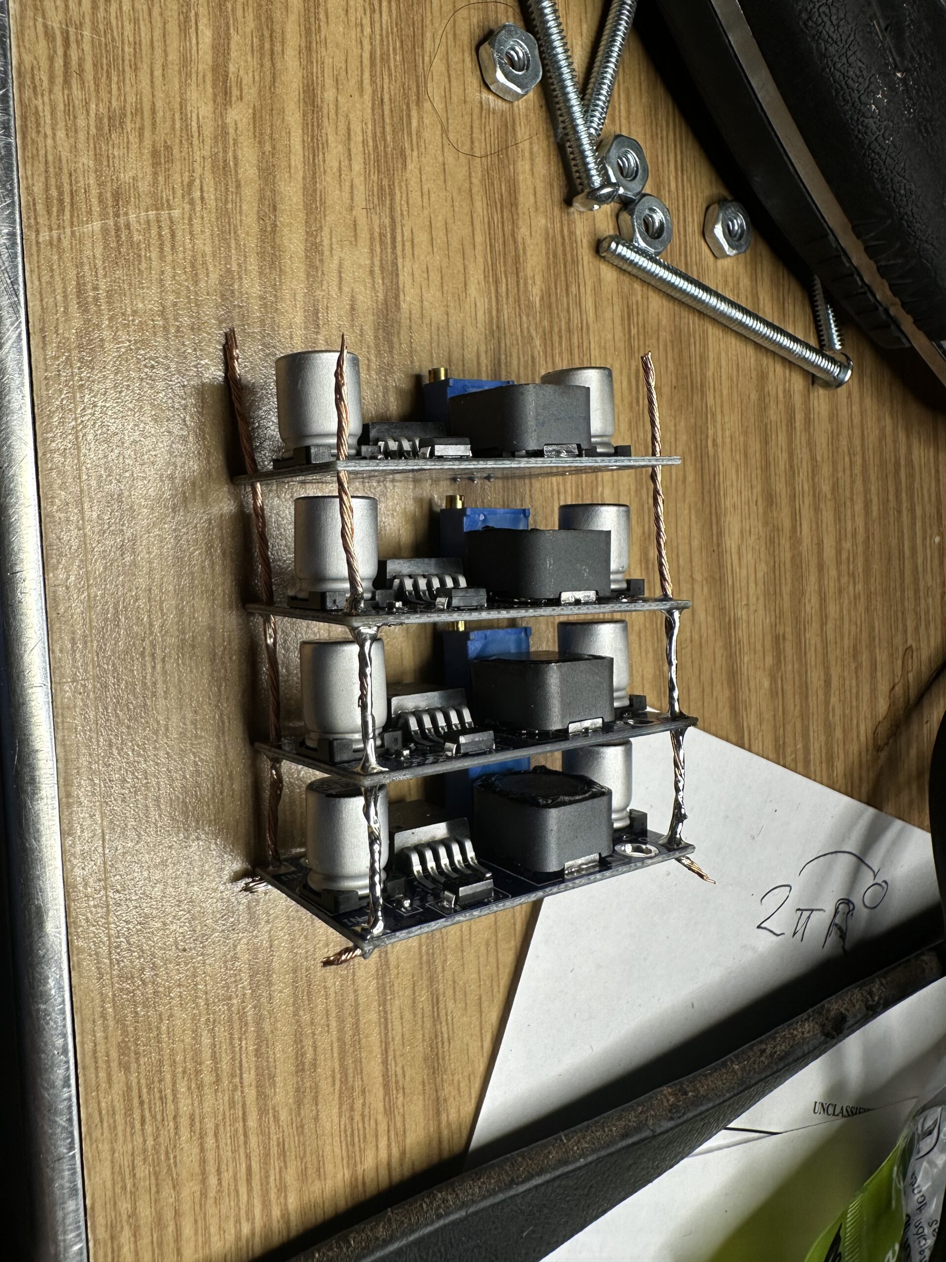
I had wired the inputs in parallel, and the output return rails in parallel. I went to apply power to test it, and smoke rolled out. Still can’t figure out what happened. So I ordered a couple more modules, and tried again.
This time, I wasn’t going to try and get fancy yet. Start small and work my way up. I applied power, and they were happy. Next – to figure out how to install them into the chassis of the Sprague. It’s all metal, so I will need to come up with an insulating installation method. Nylon screws… duct tape… hot glue… I’ll MacGyver something.
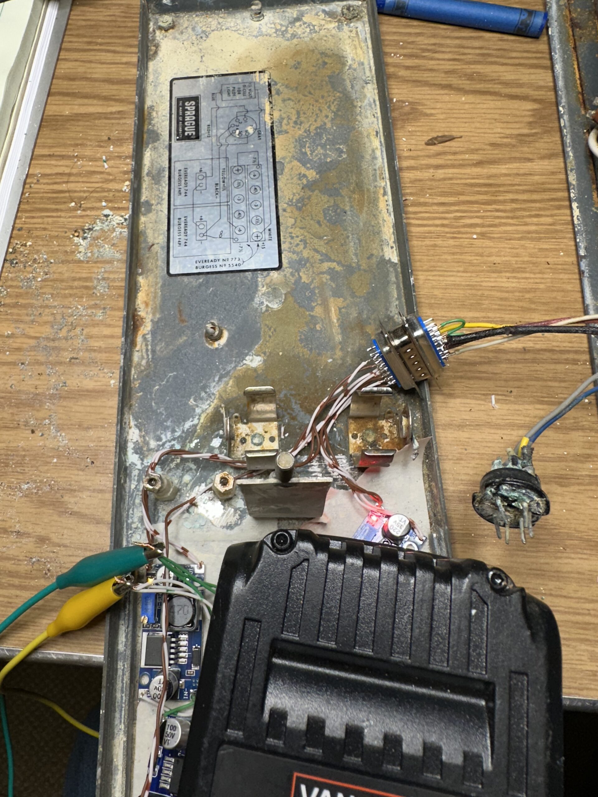
Oh yeah, forgot to mention… the original connector was also toasted due to corrosion. It was a 7 pin circular connector of some sort. A DB9 pair would have been excellent, but in lieu of that, I used a pair of DB15s I actually had on-hand. For now, this setup only has the operating voltages – I haven’t added a fourth converter for the panel lighting power yet. Fortunately, Sprague was very consistent in their wiring colors – so verifying I was using the right converter output for the right circuitry was easy. Just follow the labelling inside the back cover (shown above).
I applied power, and was treated to static! I put some headphones on, and tuned through band “F” (50 – 220 MHz), and found a whole lot of music stations! With a little more messing around, I heard some on the AM band as well, so I think it’s clear that the <65 kHz switching frequencies of my converters are not an issue, since the Sprague doesn’t start receiving until 560 kHz (one of my biggest fears from putting a switching supply in was interfering with the system – looks like it’ll work just fine!). Sorry the demo video below is quiet, but I suspect there’s a few components that might need to be tweaked inside.
Next I’ll need to tackle the 1.5V for the pilot light, and also how to permanently mount the converters, battery adaptor, and connector. I suspect the pilot light was on a separate power source, just so it didn’t affect the bias voltage, but just to be safe, I’ll give it its own converter, and wire it as if it’s isolated from chassis, even though I know the return is bonded to chassis internally, according to the schematic in the manual.
Now- let’s be honest. I’m not going to use this as my go-to to track down issues. My IC705 or even my UV-K5 portable are going to be more sensitive and more frequency agile. Bit having this on a shelf and listening to a ball game on it just sounds like a cool idea- it seems to be a bit of a museum piece – and my new power source eliminates the fear of more batteries splitting open and corroding due to disuse.