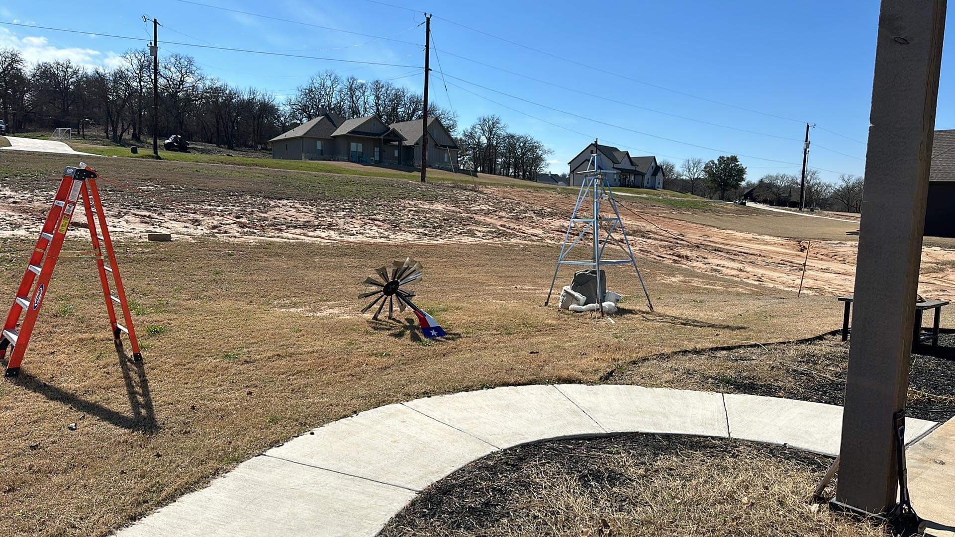
I finished the project, and did one initial test with the cord just draped on the ground, with the center support elevated a bit. Yes, the feature image is my antenna range, so to speak.
As a non-scientific comparison, I dipped a toe into the water with WSPR, so I could see how it was radiating.. more on this a bit later, too. The antenna worked, but didn’t get out quite as well as my “reference” dipole. Right now, my antenna support is low – ~10 feet off the ground, at best, so I have challenges to begin with.
This morning, I put up some supports on the ends to actually compare the basic antenna (25′ on either side, since those are the extension cords I had), and the “zig-zag” configuration with the short/ground lines shorted at the far end (remember, I’m driving the ground, and the hot/neutral are shorted inside the balun enclosure).
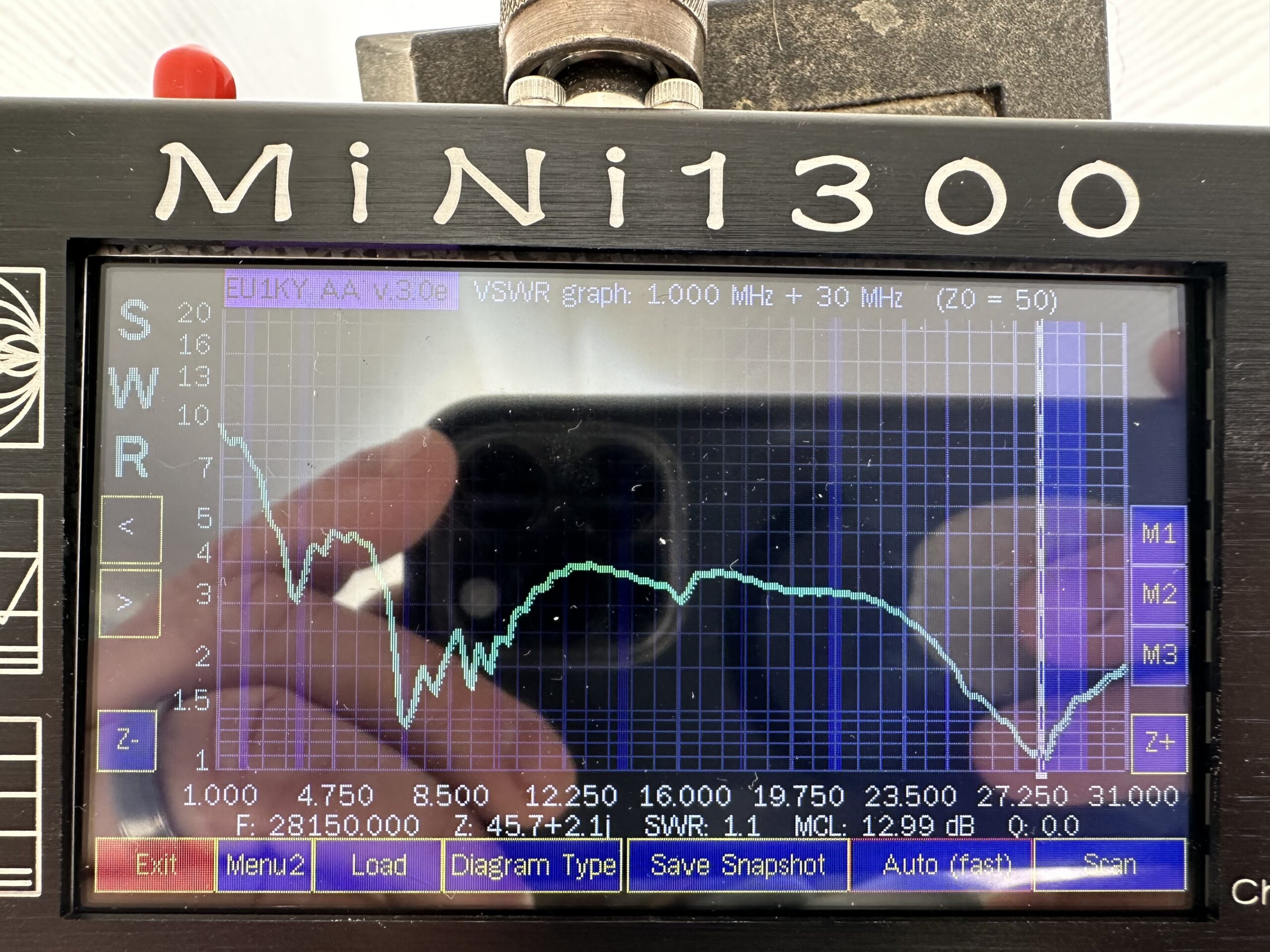
First thing I did, out of curiosity, was to throw the Mini1300 on the antenna and look at VSWR across the entire HF spectrum (1 – 31 MHz). It did surprisingly well, though I suspect part of the “matching” was the coax cable. I’ve seen that before…. The primary difference was that with the ends shorted, a SWR peak at ~10 MHz went away, and a few other things moved slightly…. but overall not much change. Below are the SWR plots… sorry for the reflection.. It was sunny out, and I can’t recall how to do screenshots on the Mini1300.

I then did the WSPR comparisons (https://www.wsprnet.org/)- note these were all done at ~11AM central time.. thus only the 20 and 10 meter tests. I tried 6 meters, but the band didn’t appear to be doing well. 40M was pretty quiet too (which seemed weird, but is not unheard of during daytime).
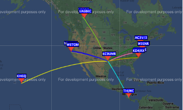
Here’s the “no-short” images – so open circuit at the end of the antenna.
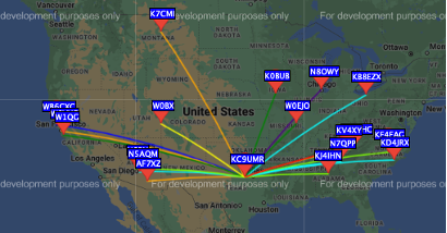
Here’s the “zig-zag” version.
Note that the zig-zag version got out, but did NOT seem to get out much better than the original version. Why is this? well, my suspicion is that the folded elements have a lot of zig-to-zag capacitance, and therefore, the antenna is much shorter (electrically) than it is physically. This also explains the similarities in VSWR plot.
So what’s next? well, I think I’m going to short all three terminals inside the balun box. This will give me more wire surface area, thus should improve bandwidth just a bit (probably not noticeably so). Since I didn’t see a notable difference in the zig-zag configuration, I won’t bother with the shorting plugs either. Now, one thing I did not have control over that I might in the field is height above ground. Would there have been better performance if I was a wavelength or more above ground? it’s possible, though I will say un-shorted performance was about on par with my normal solid-copper-wire dipole, which uses the same center support.
And finally – just a final piece of data – 1/4 wavelength and 5/8 wavelength plotted against frequency, with amateur bands called out, as well as each length plus one wavelength. Note that very few of them line up with common extension cord lengths (25, 50, 100 ft) – so a tuner will almost certainly be required in any instance… but I had planned on that anyway! The idea here is to pack one simple antenna, and then just use it as best I can! (this is assuming you have roughly matched cords on either end of the balun – OCFDs are a whole other beast). Again – my criteria for the project was simple use of off-the-shelf cords, visible (during the day), and relatively easy to untangle. This meets those requirements, as long as I have a tuner like my LDG or MFJ.
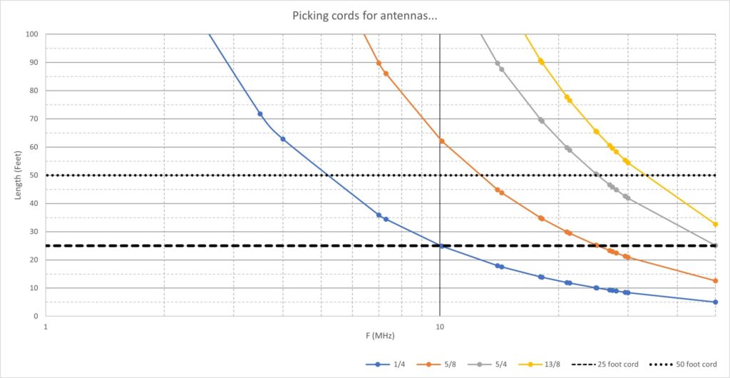
Looking at this graph brings up some interesting points.
First, for the low bands (160m) even a 100 foot cord won’t hit 1/4 wave – the 50 ohm points… but I knew this.
Next, since my plan is to short all three conductors at the feed point, would it work like a multi and fan dipole to put a 10 foot 2-prong cord at the end of a 25 foot three prong cord?
Finally, It also occurs to me that if I had a pair of 2 prong cords, I could now use those, as well., which adds to the flexibility of the setup.