(up-front disclaimer: this is AT YOUR OWN RISK… most of the project is of limited risk. Read everything and understand it before you do this)
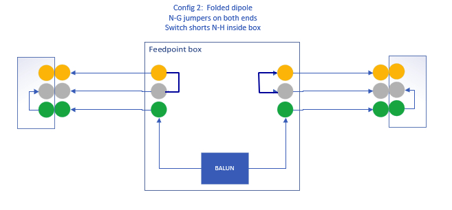
I presented this one before, and hid it way back in older posts, because it was pretty rough: https://www.kc9umr.com/wp-admin/post.php?post=280 . To reiterate, the concept is to have a feed point system that will allow the use of two off-the shelf (grounded) extension cords to make a dipole for quick field-use. The benefit of the (orange) cords is that they’re visible – quite the opposite of the normal “HOA friendly” antenna workarounds. This way, if there’s a scout outing or something similar, the cords are easily visible, so no-one walks into them accidentally, and they’re insulated wire, so RF hazards from contact are reduced. The cords also tangle less easily during transit than wire… and finally, to make a longer antenna, multiple cords can be strung together. Click the images below to see the full configurations possible as I’ve envisioned it…
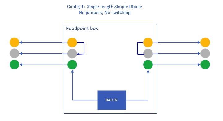
One DOWNSIDE to the approach presented here is that a non-grounded cord can’t be used as shown above. To combat this, a double pole double throw switch could be installed in the balun enclosure, tying the feed point to either the neutral or ground conductors, though the “folded” configuration would still not be possible, but it would make the end product more flexible, though ungrounded cords are usually much shorter.
More safety notes: This is intended for QRP work – not for amplifiers and high power… I’d even hesitate to run a full 100W in some cases. The dielectric withstand of a household extension cord is maybe 300V… when you start running high power into unknown matches, the voltage peaks at different parts of the antenna will vary widely. If an arc-over were to occur, the cord could be compromised, and short out when used at lower voltages later on.
Now on antenna performance: There will be some parasitic coupling between the driven wire and the non-driven wires when the end plugs are not installed. I haven’t even tried to model these. Moreover, when the shorting plugs ARE installed, and the elements are folded, there will almost certainly be some capacitive effects between the portions of the wire, thus eclectically shortening the elements – so don’t expect a pair of 25 foot extension cords to act like 75 feet of straight wire and be resonant at 3.5 MHz – it will likely be higher. I’ll do some testing when time allows to see what this really looks like electrically.
I cleaned up and revised the concept a bit for a cleaner product, and something that looked less like a fire hazard.
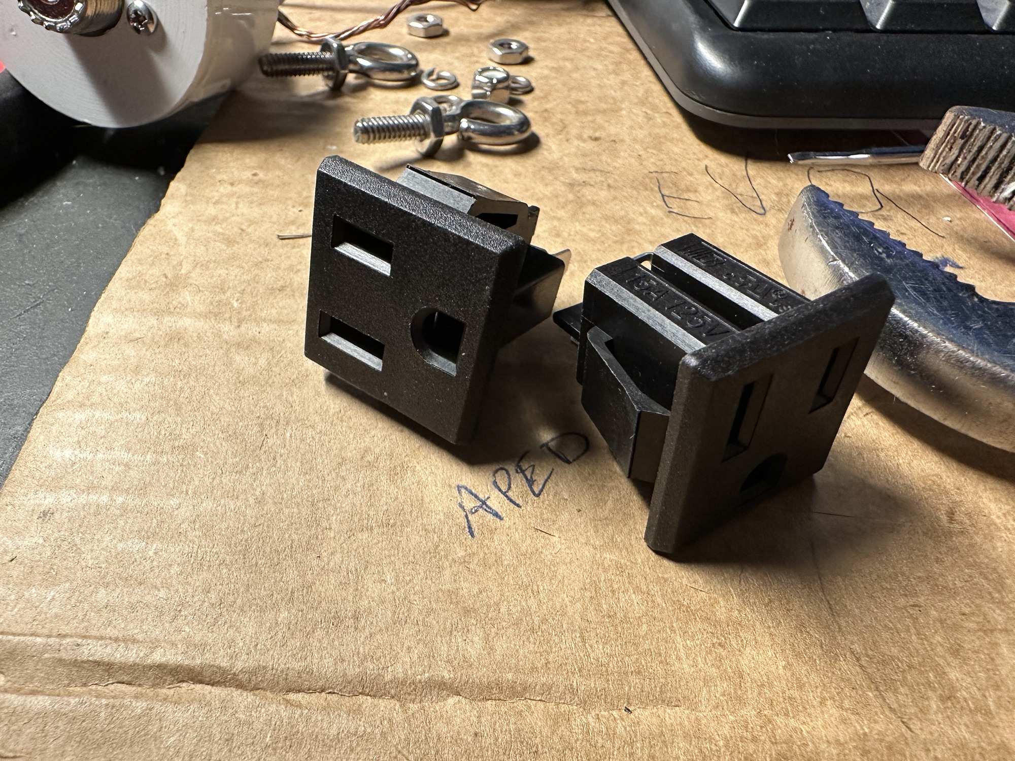
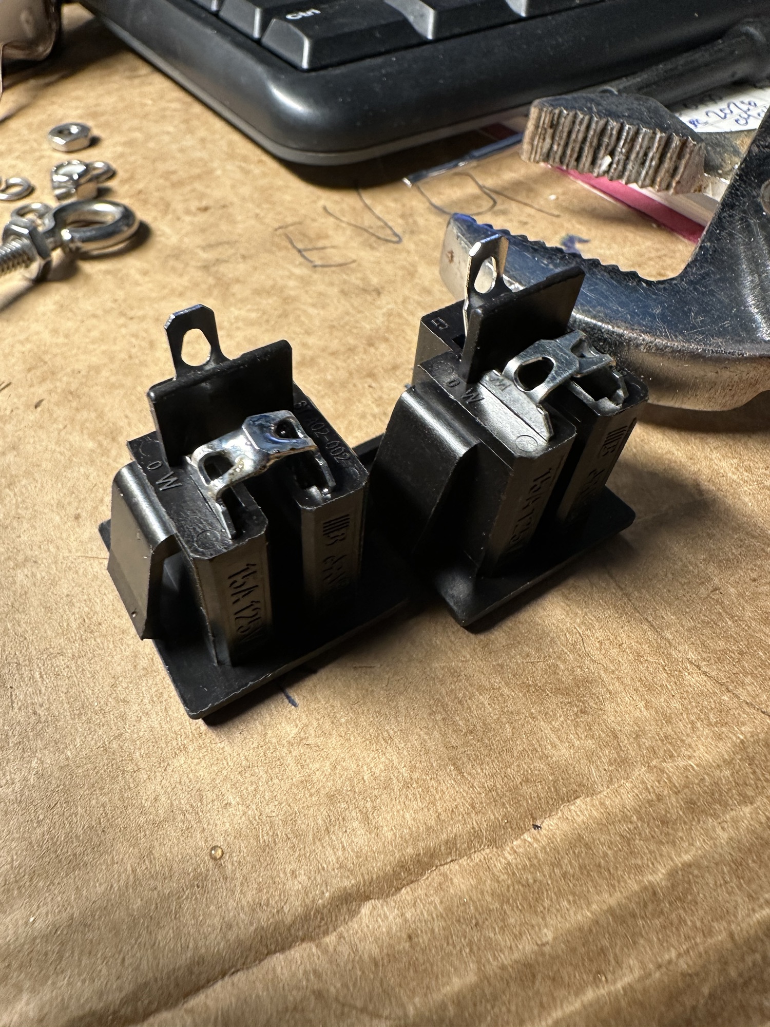
First, I got some individual outlets for panel mounting. These are cheap on amazon, and are also likely available at your favorite surplus store (all electronics is gone…). As you can see, this is in the middle of some other disassembly. When I still owned an SB220, I had one of these in the rear panel.
Based on the design, the hot and neutral terminals need to be shorted. This is an easy task with the specific ones I chose. As you can see below, I just folded the terminals over one another and soldered them together. Done.
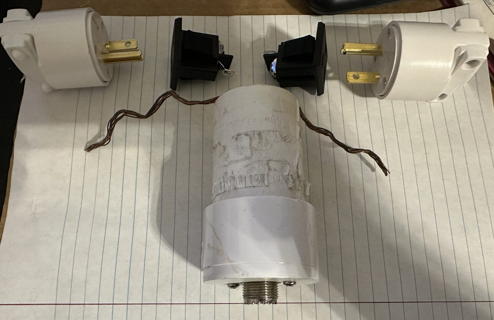
The Balun was another challenge. I had one up outside that I’ve been concerned about because it was not even remotely sealed well – the wires just punched out of the PVC insulator through holes. I wasn’t keen on that, so I swapped it out with a more weather-sealed version, and proceeded to disassemble the un-sealed version. I ended up salvaging the feed point, balun, and some hardware. The plan is to get some PVC from Lowe’s, and a PVC “Tee” fitting to house the 115V jacks, and even put the original eye bolts back in for added flexibility (And to secure the extension cords – 115V jacks don’t lock!). I’ll keep the original bottom feed point, and maybe even the housing – and just “fix” the top portion. Here’s a photo of (most of) the pieces:
Finally.. the sketchy part. The Neutral-Ground shorting connectors. These are *NOT* something I would think UL or any other accrediting agency would approve of, and I would do everything possible to label them as “antenna use only, not for home-use”.
!!!! THESE ARE BUILT AND USED AT YOUR OWN RISK! I take no responsibility for anyone building these and then plugging them into their wall socket and causing damage !!!!
I got a couple 3-prong replacement plugs from Harbor Freight for $2.99 each. Cheap, and useable. I then used my soldering iron to heat the HOT conductor (brass screw) until it was hot enough to push out of the housing. It now no longer exists. This is one step towards safety.
I’ve toyed with the idea of using a fuse to jumper the neutral and hot lines, just in case someone were to plug it into an improperly wired home outlet, because, well, let’s face it, dumb things happen. The issue I’ve run into has been what size fuse is needed? 100W could be delivered to your antenna – and what impedance is it presenting? At any rate, here’s the result:

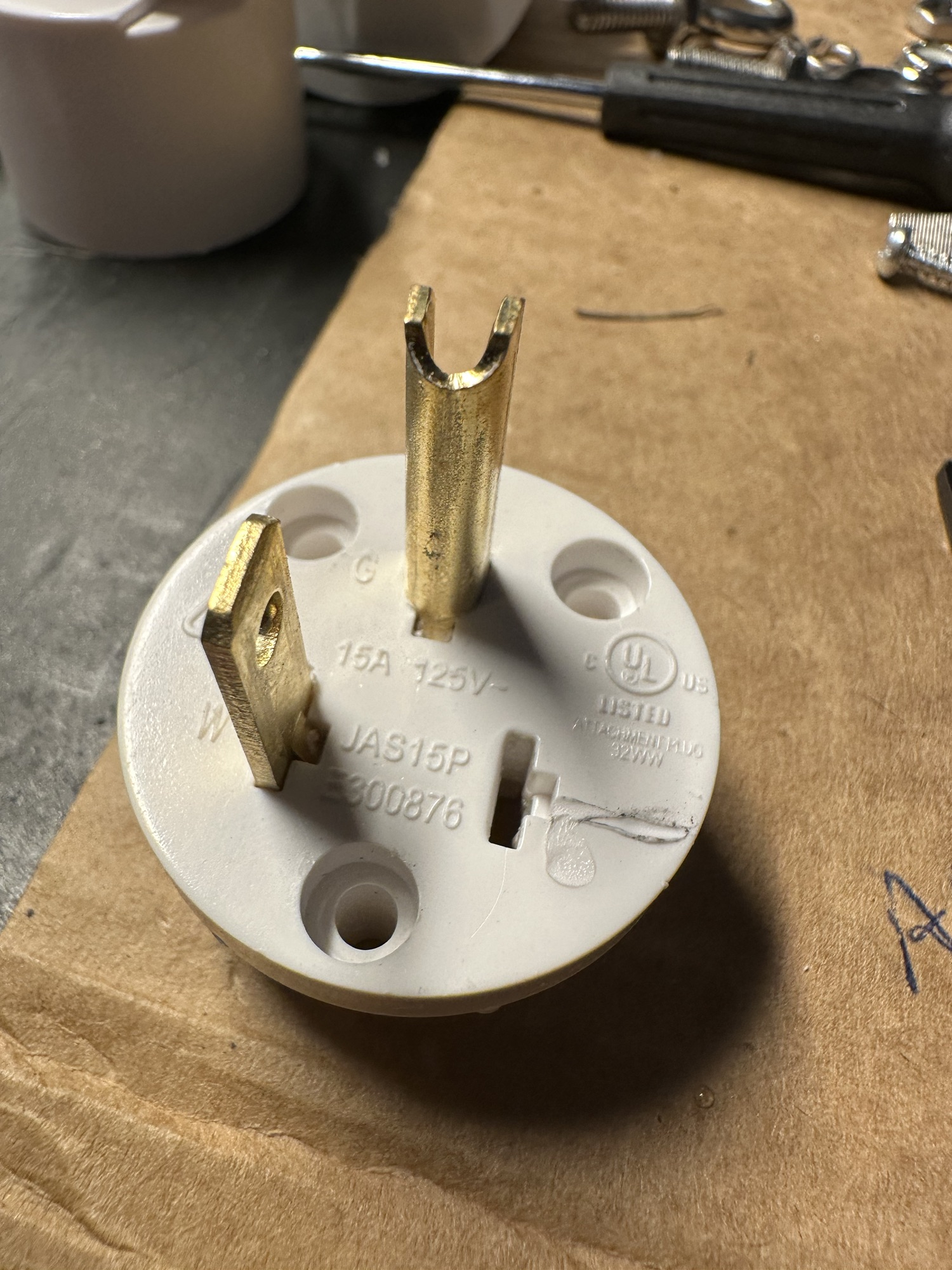
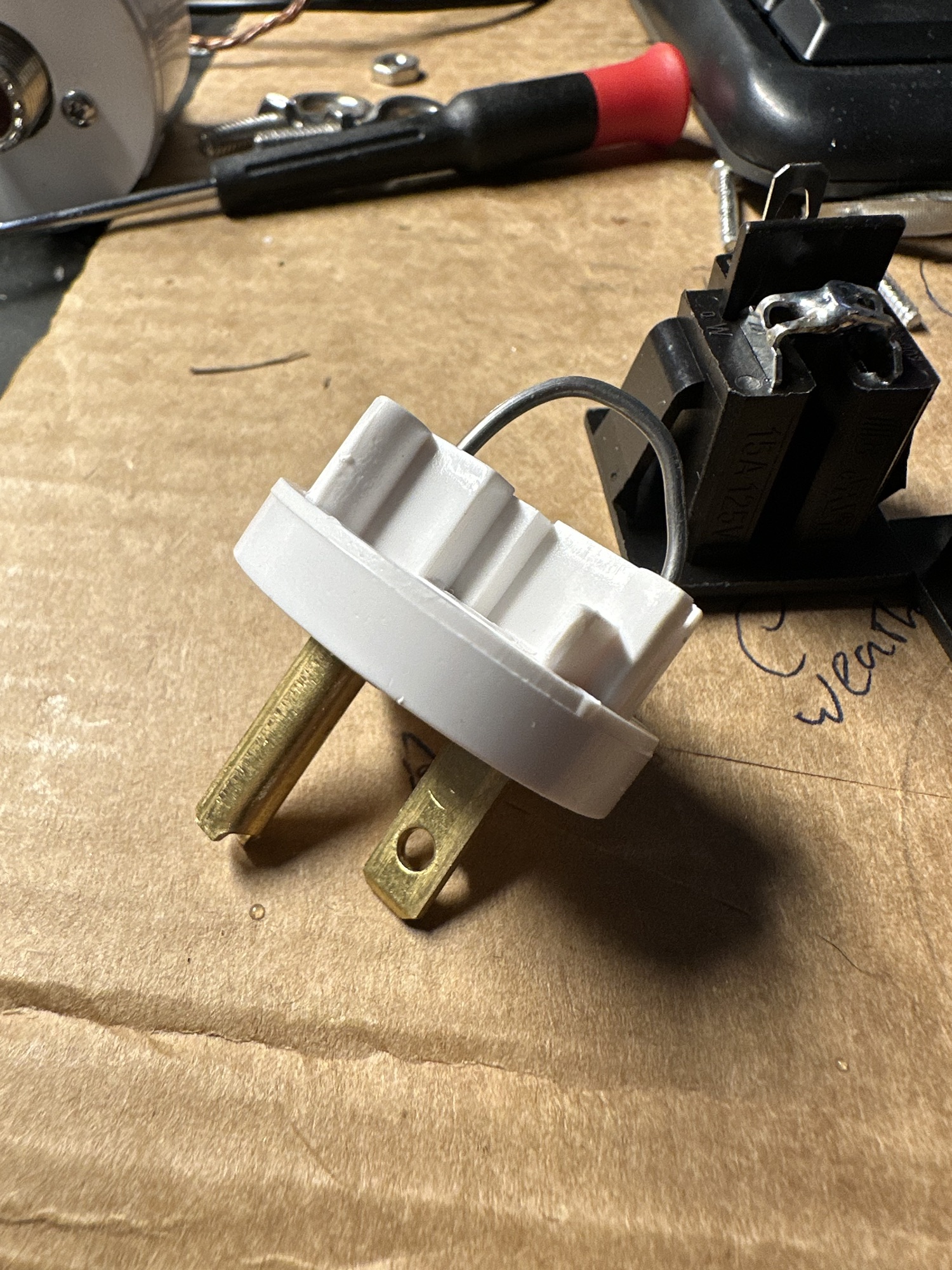
And again, note – the hot lead has been removed from the plug altogether. The reason I chose the wiring configuration I used was that IF someone were to plug one of the jumpers into a wall, it would only connect ground to neutral – which is tied together inside your electrical panel already. Per NEC, there shouldn’t be other ties in the electrical system, but it also shouldn’t hurt anything. The risk is an improperly wired receptacle would result in this being a hot to ground connection, which would be bad.

So, realistically, the RISKS here are very minimal – but because we’re using household electrical parts, there’s always the possibility of someone doing something dumb with them. The idea here is a makeshift antenna that’s generally safe to use, using off-the-shelf cables for simplicity. This is not intended to be a long-term antenna, but rather a short term field-use antenna.
And now… the final product. As you can see, I bought the wrong sized PVC fittings – I bought 1-1/2″ fittings, and the original balun used 1-1/4″… so with a heat gun, I softened the two fittings, and fitted the bottom portion of the balun into the 1-1/2″ PVC Tee. One improvement still needed is a strain relief to tie the cords to, maybe a couple eye bolts – so the cords don’t pull themselves out when strung up in a tree.


And finally – some more safety tips:
- If you look at any 115V plug (on a device or an extension cord), and it’s missing ANY prongs, DISCARD it or COMPLETELY replace it.
- If you look at a 115V plug and any prongs have been modified or damaged, replace the plug or the device immediately.
- If you see a plug that is not connected properly to a device or extension cord, DO NOT plug it in, regardless of the prong count or condition.
- This is intended as a compromise antenna for QRP work. Electrical cords have limited dielectric ratings – likely around 300V. Use of more than 100 Watts is likely to far exceed this voltage, and could make the cord unsafe for future use as an extension cord if internal arcing occurs.
- Don’t do dumb things.